Survey Deliverables Guide: Plans, Point Clouds, Orthophotos, Meshes and BIM Explained
A survey is only useful when its outputs match the decisions your team needs to make. This guide compares plans, sections, elevations, point clouds, orthophotos, meshes, photorealistic photogrammetry models, Revit and IFC models, explains their strengths and limitations, and shows how to choose a proportionate deliverable package.
- Choose outputs for the intended project decisions.
- Agree coverage, coordinates, level of detail and file formats before survey work.
- Point clouds, CAD and BIM have different strengths and limitations.
A measured survey is not finished when the site has been scanned.
It is finished when the project team receives information it can use.
For one project, that may be a concise set of floor plans and two sections. Another may need a registered point cloud, external elevations, roof orthophotos and a Revit model coordinated to a project grid. A heritage team may value detailed imagery and mesh data, while a contractor may need verified dimensions around a handful of critical interfaces.
The capture method matters, but the deliverables determine how the survey enters the wider project.
The best survey package is not the one with the most files. It is the one that gives each project discipline enough reliable information to make its next decision.
TL;DR — Which survey deliverables do you need?
- Choose deliverables according to the decisions the survey must support, not simply the technology used to capture the site.
- Plans, sections and elevations remain the most accessible outputs for planning, design, pricing and construction.
- A registered point cloud preserves dense three-dimensional survey evidence but usually requires specialist software and confident users.
- Orthophotos provide measurable, image-based records of façades, roofs, floors or detailed surfaces.
- Meshes are useful for complex shape and visual context, but they are not automatically suitable as precise design models.
- Photorealistic mesh models add photographic colour and texture to a surface model, making visible fabric easier to review; realistic appearance does not establish measurement accuracy.
- Revit and IFC models support model-based coordination when scope, level of detail and modelling tolerance are defined clearly.
- More deliverables do not automatically create more value. Every additional format brings production time, file-management requirements and interpretation choices.
- The best package is usually a small, coordinated set of outputs that the project team can open, understand and use confidently.
What are survey deliverables?
Survey deliverables are the drawings, datasets, models, images and supporting information issued after site capture and processing.
They translate measured evidence into forms that different users can understand.
Typical deliverables include:
- floor plans;
- roof plans;
- reflected ceiling plans;
- sections;
- internal and external elevations;
- topographical drawings;
- registered point clouds;
- orthographic imagery;
- photographic records;
- textured meshes;
- Revit models;
- IFC models;
- schedules, control information and coordinate data;
- DWG, PDF, E57, RCP, RVT, IFC and other agreed file formats.
They are not interchangeable.
A point cloud may contain far more measured information than a CAD plan, but a planner or architect may find the plan substantially more useful. A mesh may communicate a complex surface clearly but be awkward for precise drawing production. A Revit model can support coordination but also introduces modelling assumptions that do not exist in the raw survey data.
Choosing well requires an understanding of both the project and the information type.
What does the survey need to achieve?
At Geo Scan, this is the first question we like to ask. Understanding how you would define a successful survey lets us recommend survey information that is fit for purpose, with the right coverage, detail and formats.
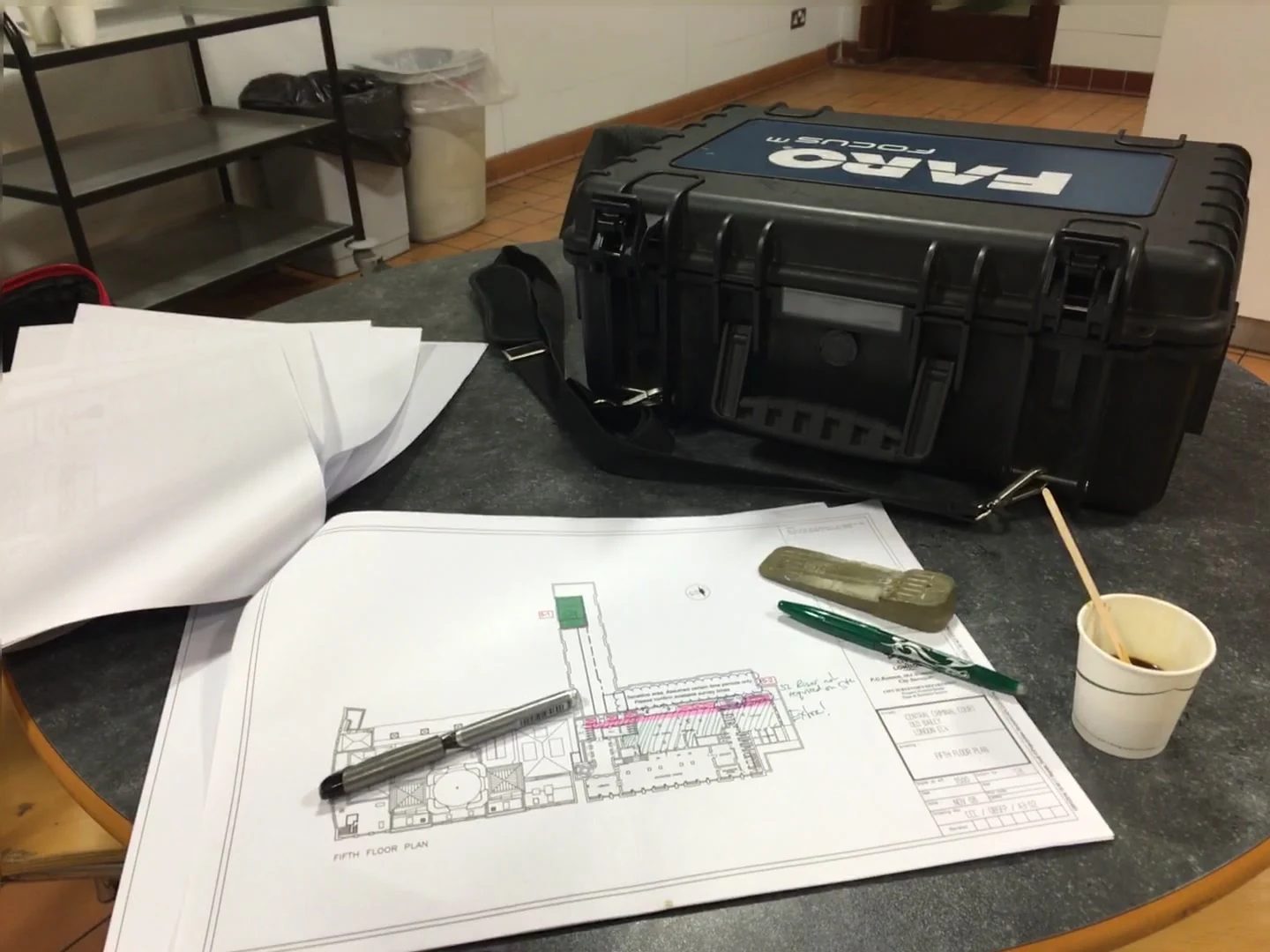
For example, are you developing a design, checking a critical clearance, preparing a planning application or recording an existing asset? Those answers shape both the survey and its outputs. You do not need to arrive with a finished technical specification: tell us the task, who will use the information and which software they work in.
Before asking whether the team needs DWG, E57 or IFC, establish what the survey must help somebody do.
Common decisions include:
- preparing a planning application;
- developing an architectural design;
- coordinating structure and services;
- checking spatial fit;
- pricing refurbishment work;
- fabricating components against existing geometry;
- recording completed work;
- managing an estate or asset;
- documenting heritage fabric;
- investigating a façade, roof or plant space;
- assessing areas, levels or capacity;
- providing a reliable base for future surveys.
The same building might justify a very different package for each purpose.
A design team may need conventional drawings plus the point cloud for occasional verification. A facilities team may need a structured model and asset information. A façade consultant may need orthophotos and elevations. A small planning project may need only clear plans, elevations, sections and a site plan.
This outcome-led approach also keeps quotations meaningful. The survey package covers preparation, site attendance, capture, processing, interpretation, deliverable production and quality assurance—not an arbitrary number of CAD days.
Survey deliverables at a glance
| Deliverable | Best suited to | Principal strength | Main limitation |
|---|---|---|---|
| Plans | Layout, planning, design and area work | Familiar, clear and easy to annotate | A single horizontal view cannot explain all vertical relationships |
| Sections | Heights, levels, structure and spatial relationships | Communicates vertical geometry clearly | Only represents the chosen section positions |
| Elevations | Façades, openings, internal walls and equipment | Clear face-on record for design and review | Hidden or obstructed features remain unavailable |
| Point clouds | Verification, coordination and future interrogation | Preserves dense 3D measured evidence | Large files and specialist software can create barriers |
| Orthophotos | Façades, roofs, surfaces and heritage fabric | Measurable image with rich visual detail | Surface visibility and projection geometry affect usefulness |
| Meshes | Complex form, context and visualisation | Intuitive representation of irregular geometry | Can be heavy, noisy or unsuitable for precise design operations |
| Photorealistic mesh models (photogrammetry) | Heritage records, surface appearance and visual review | Combines three-dimensional form with photographic colour and texture | Image coverage, surface characteristics and survey control affect the result |
| Revit model | BIM coordination and model-based design | Structured, navigable building information | Requires defined modelling rules and idealises real geometry |
| IFC model | Exchange between compatible BIM platforms | Open model exchange format | Translation may not preserve every native property or behaviour |
Plans
Plans are horizontal representations of a building, site or defined level.
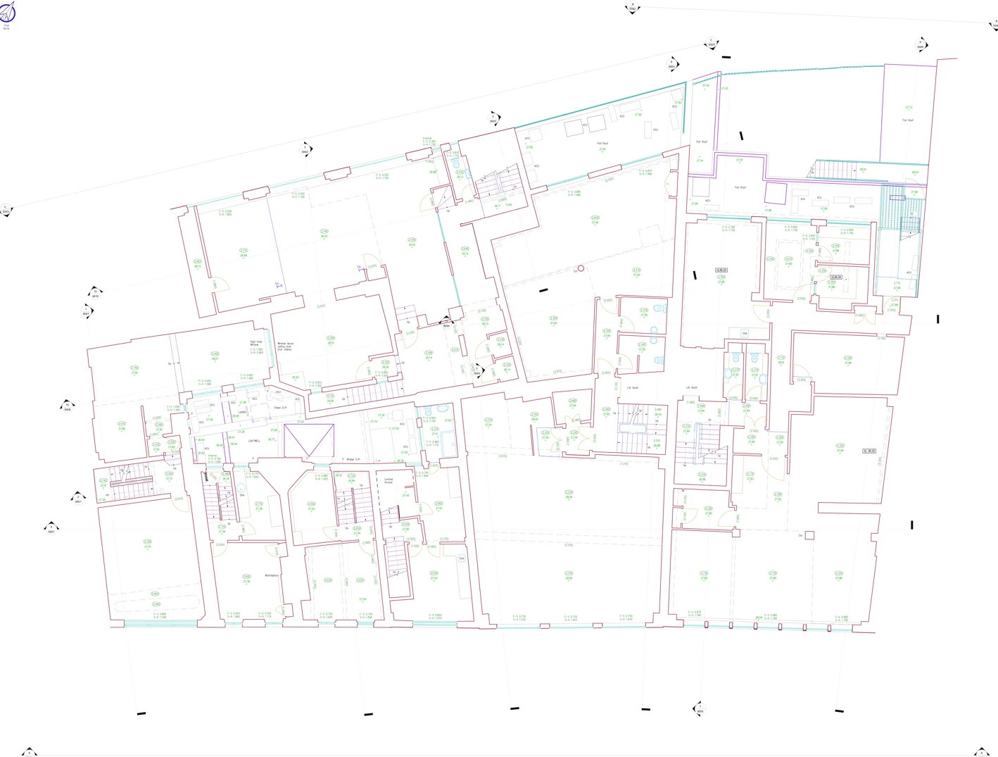
They are among the most widely used measured survey outputs because they communicate layout efficiently and work well across architecture, planning, construction and property disciplines.
Depending on scope, plans may show:
- walls, partitions, columns and structural features;
- door and window openings;
- stairs, voids and changes in level;
- principal dimensions;
- room names or use;
- fixed equipment and fittings;
- floor levels and ceiling heights;
- overhead features shown by convention;
- visible services where requested;
- grid, datum and coordinate information.
Floor plans
Floor plans establish the arrangement and relationship of spaces. They are typically the starting point for refurbishment, fit-out, planning and area work.
Roof plans
Roof plans can record pitches, ridges, valleys, parapets, plant, drainage features and access arrangements, subject to visibility and safe access.
Reflected ceiling plans
Reflected ceiling plans may show ceiling forms, bulkheads, lighting, grilles, visible services and other overhead features. An open-ceiling MEP survey requires a different scope and density of information from a general architectural RCP.
Plans are usually supplied as DWG and PDF, with scale and detail agreed to suit the project.
Do I need a floor plan, roof plan or reflected ceiling plan?
A floor plan explains the space at a floor level. A roof plan describes the roof layout. A reflected ceiling plan records the overhead arrangement. Specify the views your team will use: a floor plan does not automatically include a detailed ceiling or roof survey.
Common mistake: asking for “plans” without agreeing floors, roof coverage, annotations and ceiling detail. Identify the building extent and any critical features before capture.
Sections
Sections cut vertically through a building or site to explain relationships that plans cannot show.
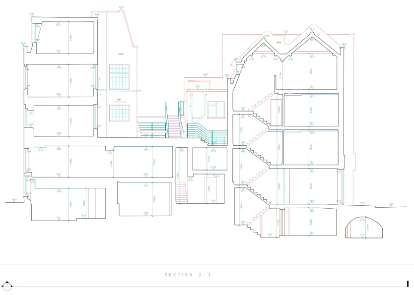
They can communicate:
- floor-to-floor heights;
- ceiling and soffit levels;
- roof geometry;
- stairs and level changes;
- foundations or below-ground structure where visible or supplied;
- openings and head heights;
- structural zones;
- adjoining buildings and external ground relationships;
- plant, ducts or services where included.
Section positions matter. A single section through the simplest part of a building may not explain a complex stair, split level or roof.
The brief should therefore identify the number, orientation and critical subjects of the required sections.
For buildings with irregular geometry, additional sections can be more useful than forcing too much information into annotations.
How many sections should I request?
Start with the questions your design needs to answer. A stair, split level, roof junction or relationship to neighbouring ground may each need a different cut. Mark proposed section lines on a plan and agree them with your surveyor.
Common mistake: leaving the cut positions undefined. Additional drawings are useful only when they explain a relationship the existing views miss.
Elevations
Elevations are face-on representations of vertical surfaces.
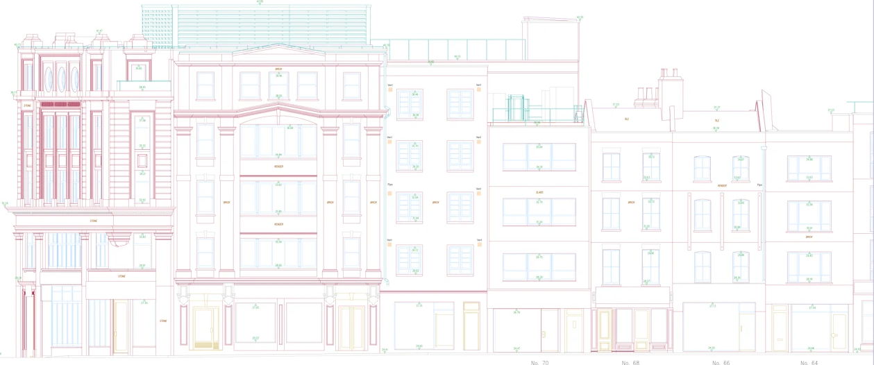
External elevations commonly record:
- openings;
- architectural features;
- façade lines and materials where observable;
- levels;
- roof and parapet relationships;
- rainwater goods;
- visible services;
- adjacent context where included.
Internal elevations may show:
- wall geometry;
- doors and openings;
- fitted joinery;
- sanitaryware;
- equipment;
- wall-mounted services;
- decorative or heritage features.
Elevation scope should be explicit. “Four elevations” might mean the four principal external faces, but party walls, enclosed courtyards, light wells, side returns or obscured boundaries can make that assumption unreliable.
Plans, sections and elevations together create a coherent 2D drawing package. See As-Built Drawings Explained for how measured drawings differ from design, construction and record information.
Does an external elevation package include internal walls?
Internal and external elevations are different outputs. For internal work, specify the rooms and wall faces; for external work, identify courtyards, returns, light wells and adjacent context as well as principal façades.
Common mistake: assuming every face is visible or safely accessible. Obstructions and survey limits should be recorded rather than completed by guesswork.
Registered point clouds
A point cloud is a three-dimensional collection of measured points representing visible surfaces.
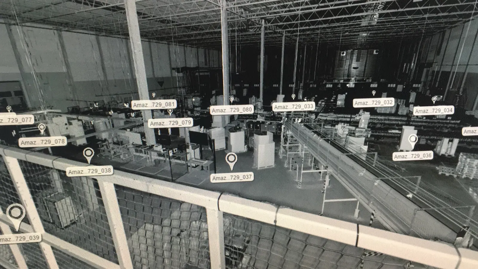
When individual scan positions are registered into a common coordinate framework, the result can provide a dense spatial record of the surveyed environment.
Point clouds are valuable because they allow users to:
- inspect geometry beyond the specific views drawn initially;
- measure visible features;
- review spatial relationships in 3D;
- coordinate new work around existing conditions;
- return to captured evidence without immediately revisiting site;
- produce further drawings or models later;
- compare surveys taken at different times.
Common delivery formats include:
- E57 — an open exchange format widely used for 3D imaging data;
- RCP/RCS — Autodesk ReCap formats used across Autodesk workflows;
- LAS/LAZ — common in geospatial and aerial-data workflows;
- PTS/PTX — text-based formats that can be useful for exchange but may create large files;
- proprietary project formats where specifically required.
A point cloud is not automatically convenient for every recipient. File size, computing resources, software compatibility, coordinate magnitude, colour requirements and data-management capability should be considered before issue.
It is also important to distinguish:
- registered data from unregistered individual scans;
- cleaned or unified clouds from raw instrument data;
- colourised points from intensity-only data;
- local coordinates from site or OS-related coordinates;
- the survey archive from a production-ready exchange dataset.
For the service context, see Point Cloud Surveys. For accuracy, registration and control, read Terrestrial Laser Scanning Accuracy.
Do I need the point cloud as well as CAD drawings?
Request both when your team wants clear working drawings and can also use the measured geometry for verification or later production. A cloud-only package can be proportionate when the recipient has its own capable CAD or BIM team. Check formats, software and computing capacity first.
Common mistake: asking for “raw scans” when you need a registered, cleaned and organised dataset. Agree colour, segmentation, coordinates and required exchange formats. For practical compatibility, see our point-cloud file formats guide.
Orthophotos and orthographic imagery
An orthophoto is an image presented in a defined plane and scale so that users can examine and, within the stated conditions, measure visible surface features without ordinary perspective distortion.
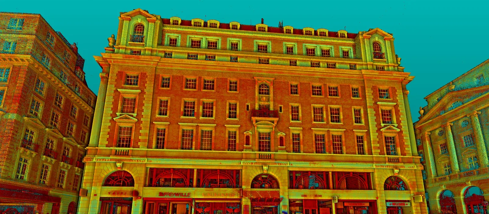
Orthographic imagery can be particularly useful for:
- façades;
- roofs;
- floors;
- ceilings;
- heritage fabric;
- decorative surfaces;
- crack or condition mapping;
- complex areas where a line drawing would omit valuable visual information.
It combines photographic richness with a geometric framework.
However, an orthophoto is not a photograph made perfectly measurable by pressing a button. Its reliability depends on source geometry, image resolution, projection plane, surface depth, occlusion, control and processing.
A flat façade is comparatively straightforward. Deep reveals, projecting elements, curved surfaces and vegetation can create hidden areas or projection effects.
Orthophotos should therefore include clear scale, resolution, orientation and any material limitations.
Can I measure from an orthographic image?
Only within its agreed projection, scale, resolution and accuracy limits. Ask for the pixel size or image resolution, reference plane and any occluded areas. A perspective site photograph is not a substitute.
Common mistake: treating attractive surface imagery as evidence of every dimension. Projecting a deep or irregular surface onto a plane can hide or overlap details.
Photographic records and scan-position imagery
Survey imagery supports interpretation and gives project teams visual context that geometry alone may not provide.
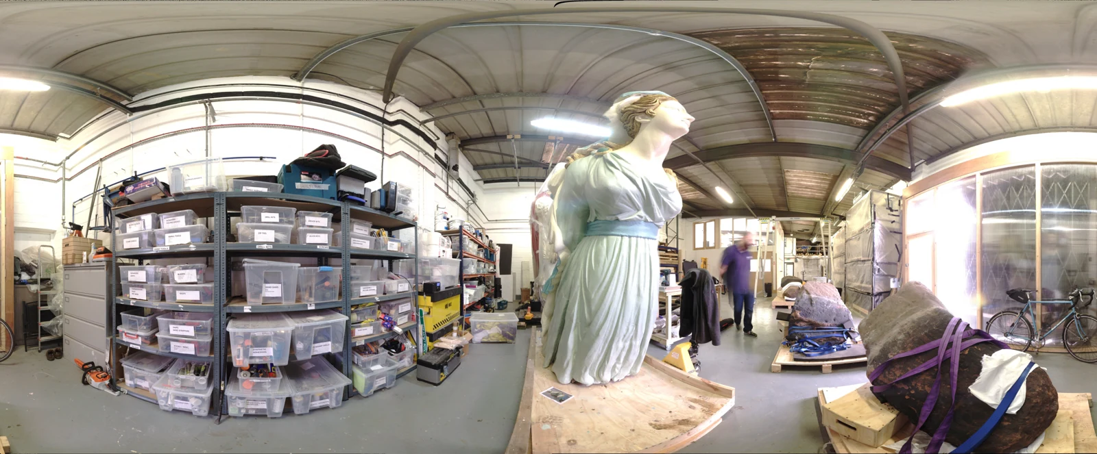
Useful imagery can include:
- site photographs;
- 360-degree panoramas from scan positions;
- high-resolution façade or detail photography;
- annotated images;
- inspection records;
- linked imagery in a web viewer.
Photographs are particularly helpful when a technician or designer needs to confirm material, condition, signage, fittings or the appearance of an obscured junction.
They should not be treated as dimensionally reliable unless produced and controlled for a defined photogrammetric or orthographic purpose.
A viewer combining scan positions, panoramas and point-cloud information can make survey data considerably more accessible to non-specialist users.
Is a panoramic viewer a substitute for survey drawings?
A viewer helps people understand the site and locate features. Drawings, point clouds or models remain necessary when the task needs controlled geometry. Agree whether the imagery is a photographic record, a hosted viewer or part of a measured dataset, together with access and hosting arrangements.
Common mistake: relying on photographs for dimensions or assuming a photograph establishes material condition. The appointed specialists should interpret what the survey records.
Meshes
A mesh represents a surface using connected polygons, often with photographic texture applied.
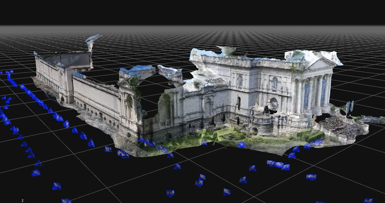
The defining feature is the surface geometry. An untextured or shaded mesh helps users inspect shape without photographic colour. A photorealistic mesh adds an image-based texture to that geometry; it is still a mesh, with a different emphasis and additional capture requirements. The next section explains that deliverable separately.
Meshes can communicate complex form intuitively and are useful for:
- heritage objects and ornamentation;
- irregular structures;
- terrain or earthworks;
- visualisation;
- digital twins and interactive experiences;
- condition or change records;
- sharing spatial context with audiences unfamiliar with point clouds.
A mesh may be derived from photogrammetry, laser-scanning data or a combination of sources.
Its apparent realism can be misleading. A visually convincing mesh may contain smoothed surfaces, holes, texture artefacts or simplified geometry. Polygon density is not the same as survey accuracy.
Before specifying a mesh, consider:
- whether measurement or visual communication is the priority;
- the required geometric resolution;
- texture resolution;
- coordinate system;
- maximum file size;
- target software or platform;
- whether decimated and full-resolution versions are needed;
- how gaps and inaccessible surfaces should be handled.
Meshes are powerful when the use case suits them. They are not a universal replacement for CAD or BIM.
Should I request a mesh or a BIM model?
A mesh represents surface shape, often with texture; BIM represents selected elements as structured objects. Irregular heritage fabric and visual context may suit a mesh, while object-based coordination may suit BIM. Some projects need both.
Common mistake: judging accuracy from visual realism or polygon count. Agree how the surface is checked, how gaps are identified and whether a lighter viewing version is needed.
Photorealistic mesh models
A photorealistic mesh combines a polygon surface with photographic colour and texture, so users can inspect visible form and appearance together.
Photogrammetry reconstructs three-dimensional information from overlapping photographs taken from different viewpoints. Photographic texture is then mapped onto the surface. Where the brief requires it, survey control or laser-scanning data can provide a measured reference alongside the imagery.
This output is particularly useful for:
- recording heritage façades, monuments and carved stonework;
- reviewing visible material changes, markings and surface detail;
- communicating complex form to teams unfamiliar with point clouds;
- creating a navigable visual record for interpretation or remote review.
How does it differ from a mesh model?
Both use connected polygons. A geometry-focused mesh is selected primarily for surface shape; a photorealistic mesh also carries photographic appearance. Photography may reveal a painted line or colour change that has little geometric relief. Conversely, a sharp-looking texture can sit on simplified or incomplete geometry.
The distinction is the intended information, not a guarantee that one output is more accurate. A textured laser-scan mesh and a photogrammetric mesh may look similar, so agree how the geometry and texture will be produced and checked.
What should the brief include?
Specify the required coverage, geometric detail, texture resolution, scale and coordinates, intended viewer and file formats. Agree whether the delivery includes the texture files, a full-resolution model and a lighter viewing version. Ask how hidden areas, gaps and reconstructed surfaces will be identified.
Photogrammetry depends on usable image detail and coverage. Reflective, transparent or plain surfaces can be difficult to reconstruct. Shadows, blurred images and obstructions may affect texture or leave incomplete areas. Additional capture or a complementary survey method may be appropriate.
Can a photorealistic model be used for measurement?
It can support measurement when scale, control, checks and suitability for the intended task have been established. A realistic viewing model alone does not demonstrate those qualities. If dimensions or fabrication interfaces drive the decision, agree the required measured information with the design team.
Our photogrammetry service explains how photographic detail and measured reference can be combined for a project brief.
Common mistake: treating photographic realism as proof of accuracy, complete coverage or material condition. Specify the geometry and visual record separately, and have the appropriate specialists interpret what is visible.
Revit models
A Revit model translates survey evidence into structured building objects.
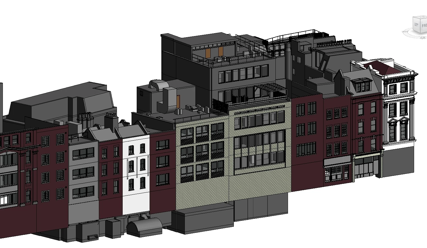
It may contain:
- levels and grids;
- walls, floors, roofs and ceilings;
- doors and windows;
- columns, beams and structural elements;
- stairs and railings;
- visible MEP systems;
- equipment and families;
- project parameters and agreed classification.
Revit can be valuable for refurbishment, multidisciplinary coordination and teams already working within Autodesk BIM workflows.
The model specification should define:
- included disciplines and elements;
- level of information and geometric detail;
- modelling tolerance;
- treatment of irregular or historic fabric;
- native family requirements;
- coordinate and shared-coordinate setup;
- phase, workset and naming conventions;
- how inaccessible or assumed geometry will be identified;
- software version.
A real wall may bow, lean and vary in thickness. A Revit wall is an idealised object. The modeller must decide how much real irregularity to represent.
More modelling detail is not automatically more truthful or more useful.
See Scan to BIM for the relationship between point-cloud evidence and project-ready BIM outputs.
Is a Revit model always better than 2D drawings?
No. Its value depends on the design team's workflow and coordination needs. If the team works in 2D, a clear DWG/PDF package may be more proportionate. A model adds value where people will actively use its geometry and agreed information.
Common mistake: using a level-of-detail label as the entire brief. List included elements, information requirements, modelling tolerance, software version and how assumptions will be identified.
IFC models
IFC is an open data format intended to support model exchange between BIM applications.

It can be useful when:
- recipients use different authoring platforms;
- an open exchange deliverable is required;
- the model must enter a wider common-data environment;
- long-term accessibility matters;
- the client specifies IFC as part of its information requirements.
IFC is an exchange, not a perfect replica of a native Revit model.
Object behaviour, parameters, classifications, geometry and appearance can translate differently between applications. The required IFC schema, model-view definition and validation process should be agreed.
Where both RVT and IFC are needed, the native model is normally the authoring source and the IFC is a checked export.
If I request IFC, do I also need the native model?
It depends on how the recipients will work. An IFC exchange may be sufficient for coordination; a team editing the authoring model may need the native file as well. Confirm the receiving software and required IFC version before production.
The examples below illustrate BIM geometry relevant to model exchange. They do not establish that a particular IFC export has been validated. That requires checking the issued file in the intended receiving workflow.
Common mistake: assuming that a successful export preserves every object, property and coordinate relationship. Agree an exchange check as part of the deliverable brief.
CAD drawings and PDF issue sets
DWG remains a practical format for editable plans, sections, elevations and topographical information.
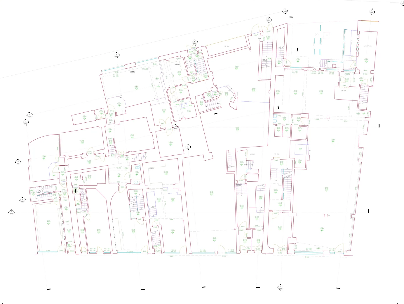
PDF provides a stable, widely accessible issue format for review, printing and controlled reference.
Supplying both is often useful:
- DWG supports design development and integration into consultant workflows;
- PDF communicates the intended plotted appearance, scale, notes, status and revision.
The PDF should not be treated as a substitute for checking the CAD deliverable, but it provides a clear reference for how the drawing was intended to be read.
Drawing packages should include appropriate title-block information, drawing numbers, revisions, scales, coordinate notes, legends and stated limitations.
Why supply DWG and PDF together?
DWG lets consultants work with the editable drawing. PDF provides a readable reference for the intended plotted presentation, notes and revision. Confirm units and scale before taking dimensions from either format, and use the current issued revision.
Common mistake: confusing editable data with an approved issue set, or assuming a PDF print remains to scale after resizing.
Topographical plans and terrain information
Topographical outputs relate the building or proposed work to the surrounding site: levels, visible boundaries, paths, roads, drainage covers, trees and other agreed features. A CAD site plan communicates those features; contours, a digital terrain model or a surface dataset may support ground and level analysis where specified.
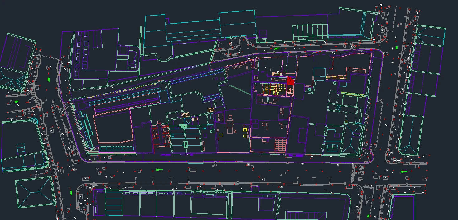
What should I ask for beyond a building plan?
Identify the external area your design relies on, the required levels and reference datum, and whether a 2D plan or usable 3D terrain information is needed. The feature list and accuracy requirements should suit the intended work. A location plan alone does not provide surveyed site levels.
Common mistake: assuming a building survey includes the entire plot or that visible drainage covers reveal underground routes. Topographical coverage and underground utility investigation need their own clear scope. See Topographical Surveys and Underground Utility Mapping.
How deliverables relate to the source survey
Survey outputs sit at different distances from the measured evidence.
A useful way to understand them is:
Measured observations → registered point cloud and imagery → interpreted drawings or surfaces → modelled objects and information
Each step can make the data easier to use, but it also introduces decisions.
A point cloud samples visible surfaces.
A CAD technician interprets those surfaces into lines, levels and annotations.
A BIM modeller interprets them again into objects with rules and parameters.
An orthophoto projects visible surface information onto a plane.
A mesh connects sampled data into a continuous surface.
This is why quality assurance cannot stop at successful site capture. Each deliverable must be checked in the form in which the client will use it.
How to choose the right deliverable package
For planning and early design
A typical package may include:
- site or location context where required;
- floor and roof plans;
- external elevations;
- key sections;
- DWG and PDF issue sets.
For refurbishment and fit-out
Consider:
- detailed plans;
- sections through critical areas;
- internal elevations where design depends on wall faces;
- reflected ceiling plans where relevant;
- point-cloud access for verification;
- a Revit model where the design team works in BIM.
For structural coordination
Useful outputs may include:
- plans and sections showing visible structure;
- critical levels;
- registered point-cloud data;
- targeted verification of interfaces;
- local details or extracted geometry.
The survey should not imply concealed structure that was not observed.
For MEP coordination
Consider:
- registered colour point clouds;
- plant-room or open-ceiling survey coverage;
- service-focused plans, sections or elevations;
- Revit MEP geometry where proportionate;
- panoramic imagery or a web viewer.
Dense environments often require more scan positions to reduce occlusion.
For façades and heritage
A package may combine:
- linework elevations;
- orthographic imagery;
- high-resolution photography;
- point clouds;
- detailed sections;
- textured meshes for complex form.
For fabrication or installation
The brief should identify the exact interfaces and tolerances.
A broad building survey may not provide the focused verification required for fabrication. Critical dimensions, datum relationships and check observations should be agreed explicitly.
For asset and facilities management
Potential outputs include:
- coordinated plans;
- a structured BIM model;
- room or asset schedules;
- linked imagery;
- an accessible viewer;
- open exchange formats where long-term interoperability matters.
The operational team’s systems and capacity should guide the specification.
Check the package before commissioning
Before instruction, ask who will open each output and what they will do with it. Confirm critical areas, grid and datum, software compatibility, issue formats and the required timescales. If a consultant is preparing the design, involve them in the brief: the survey should support their next decision.
A useful acceptance conversation covers four points:
- Coverage: which floors, elevations, roofs and external areas are included, and what is inaccessible?
- Geometry: which dimensions, levels, interfaces and tolerances matter to the project?
- Usability: can the recipients open and work with the agreed files?
- Issue control: how will drawings, models, revisions and limitations be identified?
Common mistake: deciding outputs after capture. A late request may reveal an area that was not observed or needs a different survey method. Agree likely outputs early, while keeping later changes explicit.
What should a deliverable specification include?
A concise specification should state:
- project purpose and intended users;
- survey extent and access;
- required plans, sections, elevations and other views;
- drawing scale or expected level of detail;
- critical features and interfaces;
- required point-cloud content and formats;
- model elements, disciplines and software version;
- orthophoto resolution and projection requirements;
- mesh resolution and intended platform;
- coordinate system and vertical datum;
- layer, naming and title-block standards;
- issue formats and revision requirements;
- exclusions, assumptions and inaccessible areas;
- programme and review stages.
This does not need to become an enormous technical document for every project. It needs enough clarity to prevent different parties imagining different outputs.
A practical route from brief to usable information
First, describe the purpose. Tell us the project task and who needs the information. Share an existing brief, marked-up plan or consultant requirements if you have them.
Then, agree the outputs. We can help distinguish essential views and datasets from optional additions, together with coverage, formats, coordinates and critical features.
Finally, check the issue. The package should identify what was surveyed, how the outputs are referenced and where access or visibility limits apply. The recipient should be able to understand the files without reconstructing the original conversation.
This guide supports that conversation; the project-specific survey specification remains the document defining the commissioned work.
How Geo Scan defines measured survey packages
Geo Scan scopes deliverables around what the client needs to achieve.
A complete measured survey package can combine:
- preparation and access planning;
- site attendance;
- survey control;
- terrestrial laser scanning and appropriate supplementary observations;
- registration and processing;
- interpretation;
- plans, sections and elevations;
- point-cloud, orthographic, mesh or BIM outputs where required;
- checking and quality assurance;
- coordinated issue files.
This package-based approach keeps the focus on the finished outcome.
It also creates a clear relationship between capture and production. The team collecting the information understands what the final drawings, datasets or models must communicate.
Related Geo Scan services and guidance
For more detail on individual survey outputs and their source information:
Choose information your team will actually use
Survey technology can produce extraordinary quantities of data.
The commercial and technical value lies in deciding what should be retained, interpreted and delivered.
For many projects, the answer is not one output. It is a coordinated combination:
- drawings for everyday clarity;
- point-cloud evidence for verification;
- imagery for context;
- a model where structured 3D coordination creates genuine value.
The right package gives the team enough information to move forward confidently, while avoiding unnecessary production and formats that sit unopened after issue.
Clear scope at the beginning leads to clearer information at the end.