Refining scan registration for cladding replacement elevations
At Huller and Cheese in Bristol, a cladding replacement survey needed clear panel detail and a dependable connection between high-level and ground-level scans. Registration refinement reduced the overall reported error by 17.9%, with visibly better alignment during inspection.
The problem: detailed façades need dependable alignment
A cladding replacement team needs more than a recognisable building outline. Panel joints, openings and changes in the façade must remain clear when scan data is combined and translated into elevation drawings. High point density helps capture those features; the registration framework determines how consistently the separate views fit together.
At Huller and Cheese, Geo Scan surveyed from high and ground-level positions and from across the canal in Bristol. The survey requirement was to connect this coverage into a useful geometric record for cladding replacement. The technical challenge was preserving alignment on the façade itself across a network of very different viewpoints.
This case study focuses on the problem solved in processing: identifying weaker scan connections, refining the registration around relevant common geometry, and checking whether the result improved.
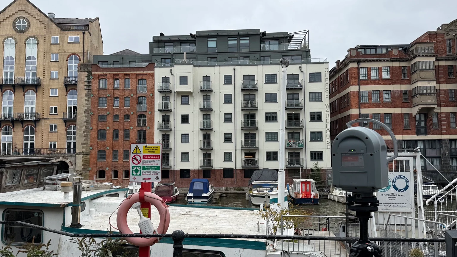
Scanning from across the canal provided a direct view of the façade and upper levels.
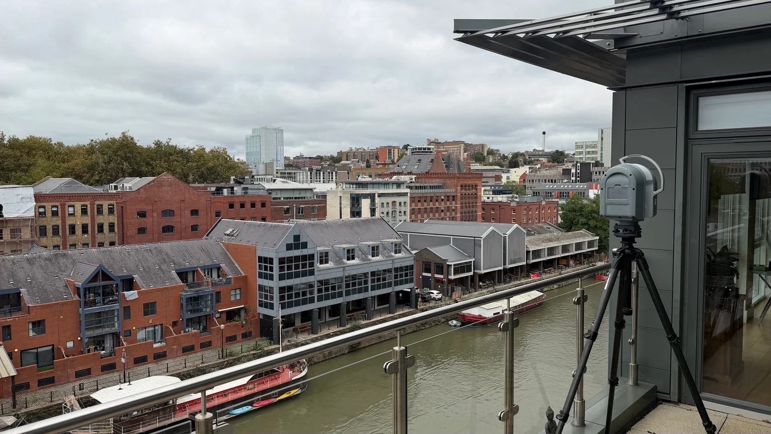
A high-level viewpoint added coverage that needed to connect consistently with the ground-level survey.
The result at a glance
The overall cloud-to-cloud error reported by the software fell from 2.9575 mm to 2.4270 mm: a reduction of 0.5305 mm, or 17.9%. Across the 206 unique scan pairs present in both reports, the equally weighted mean error fell by 19.4%.
The surveyor also reported visibly much better alignment during quality assurance and inspection. Taken together, the numbers and the visual inspection support the decision to spend time refining the registration before preparing the elevations.
These are registration residuals: measures of agreement within the scan network. They do not establish absolute survey accuracy, an agreed drawing tolerance or building-safety compliance.
Connecting high-level scans with canal-side coverage
The capture needed enough resolution to distinguish cladding panels and visible detail at high level. Those observations also had to connect with the ground-level scan framework. A dense scan can still be poorly positioned relative to another scan, so coverage and registration were considered together.
Access across the canal provided another view of the building, but introduced longer-range connections into the dataset. Geo Scan used common visible points on the opposite side to connect the observations, then scanned back across in the other direction. This created shared geometry between the viewpoints rather than treating the far-bank data as an isolated set.
Long-range scanner capability makes these viewpoints possible. The density and usefulness of the returned data still depend on distance, angle, surface and visibility. The actual canal crossing distance and project-specific scanner specification are not stated here.
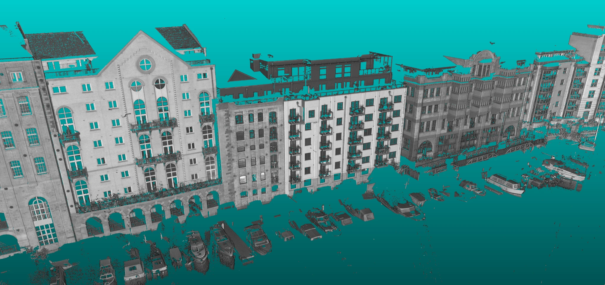
Production point-cloud view from across the canal. Captured façades, balconies and upper levels show the geometry available for inspection and elevation preparation.
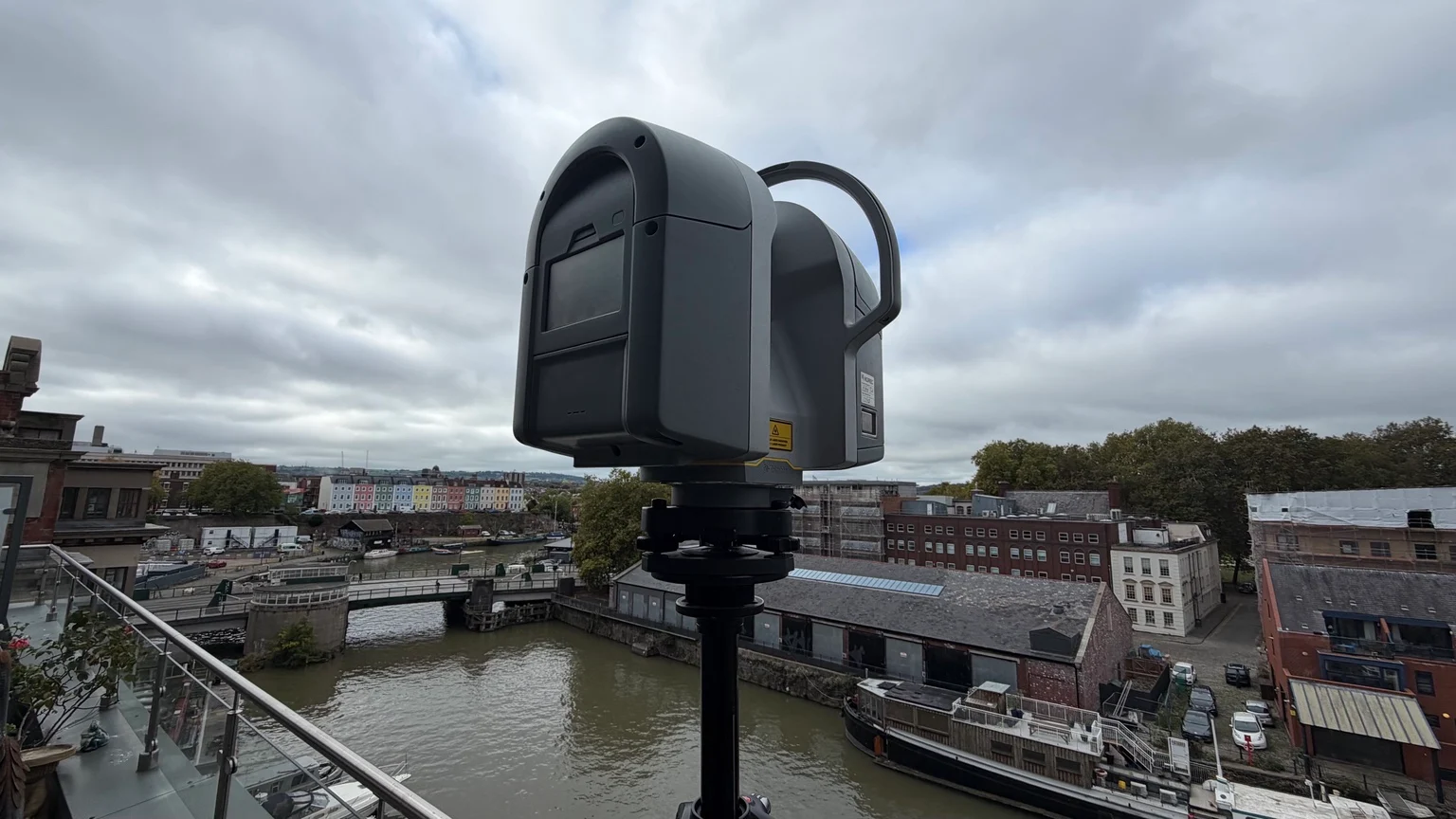
High-level scanning combined detailed capture with common geometry linking the different viewpoints.
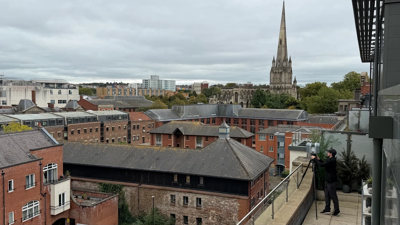
The surveyor captured the building from an elevated position as part of the connected scan network.
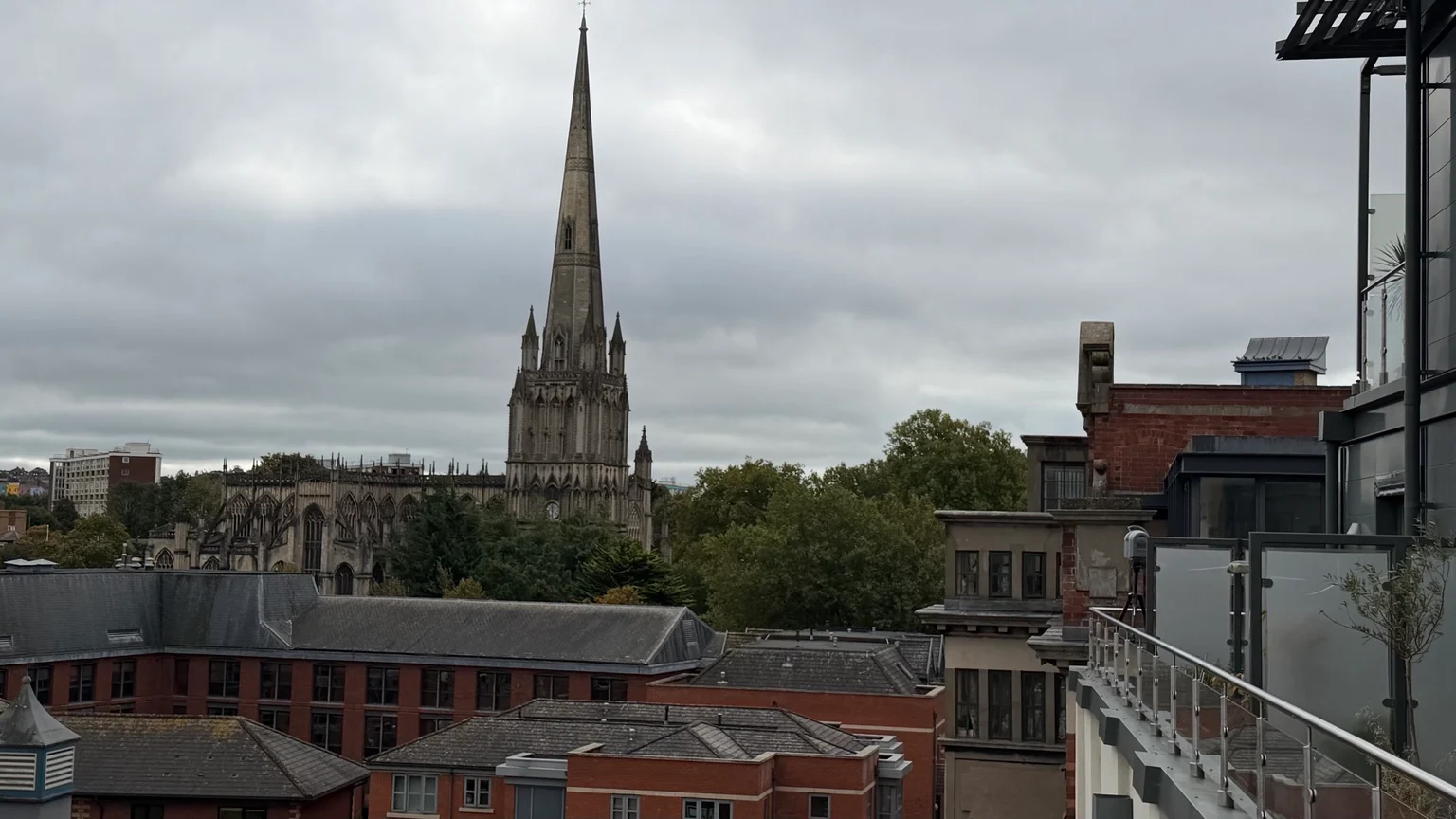
The wider surroundings show why high-level scans contain geometry beyond the façade being drawn.
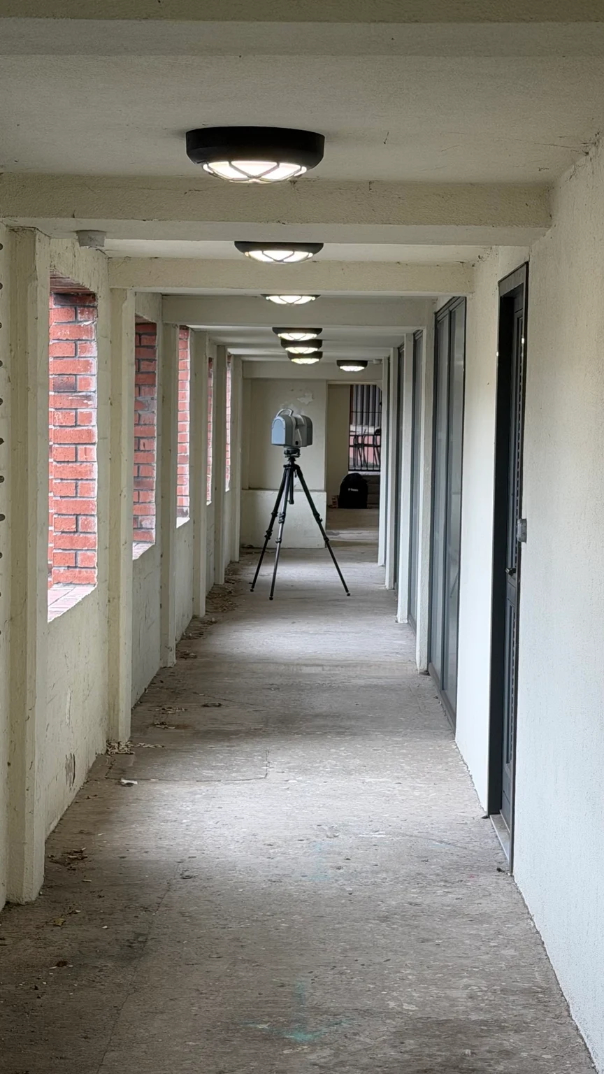
A more enclosed scan position formed part of the project capture. Its station number is not identified in the report comparison.
Why neighbouring scans were not the whole QA story
During registration review, nearby scan connections showed low residuals while connections involving more distant scans showed higher residuals. That pattern prompted a closer inspection of the network. A reassuring local fit was insufficient evidence that the façade observations agreed across the whole survey.
The review concentrated on the subject required for the elevations. Using the full 360-degree surroundings in the high-level scans risked allowing geometry away from that subject to influence the fit. The concern was the resulting alignment of the building detail, not simply the amount of overlap available.
The station identifiers in the report provide traceable comparisons. Without the scan-position plan, they cannot independently identify which station was high-level, ground-level or across the canal.
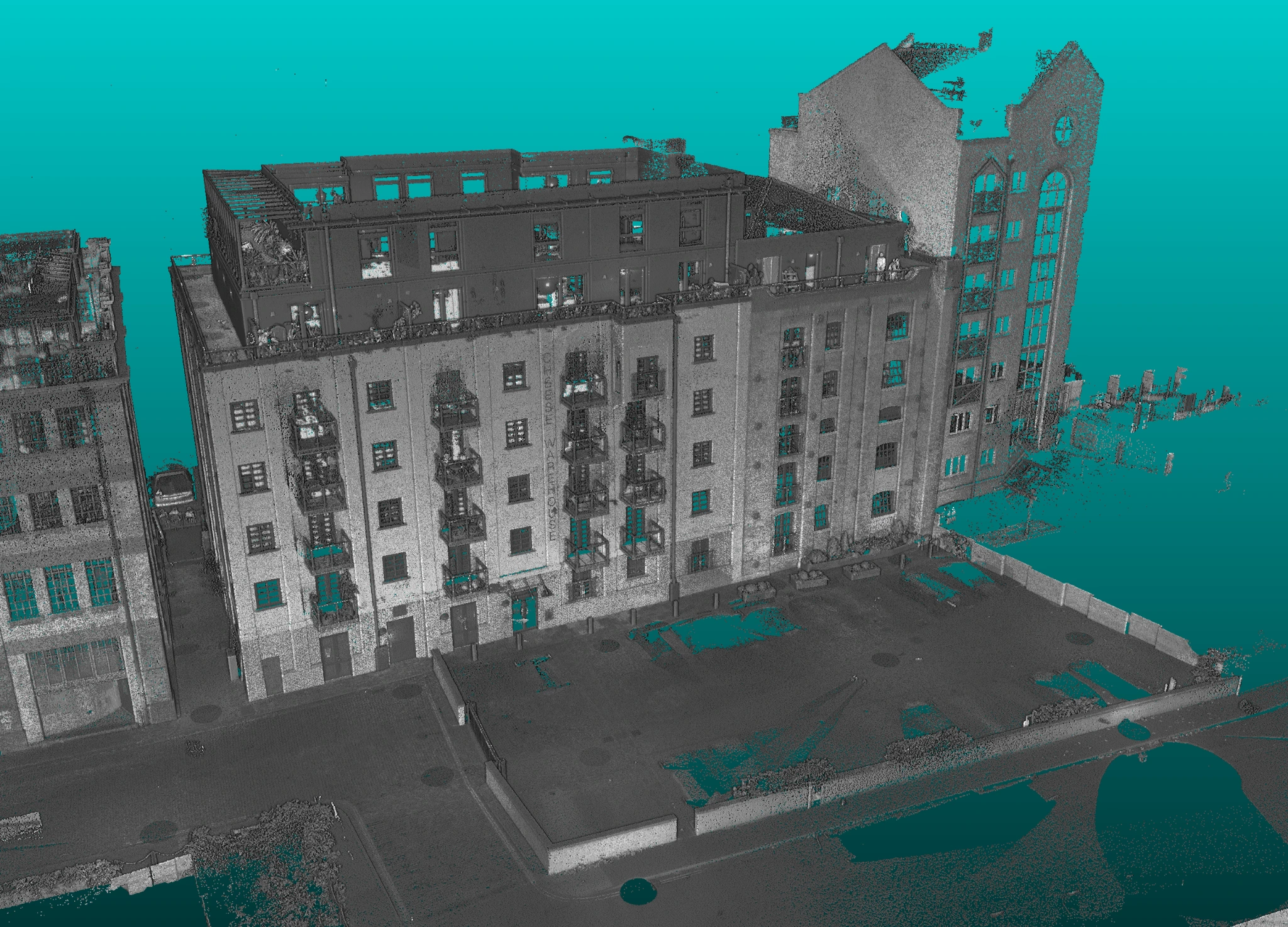
The production point cloud records visible windows, balconies and façade surfaces. This perspective view shows building detail for inspection and elevation preparation.
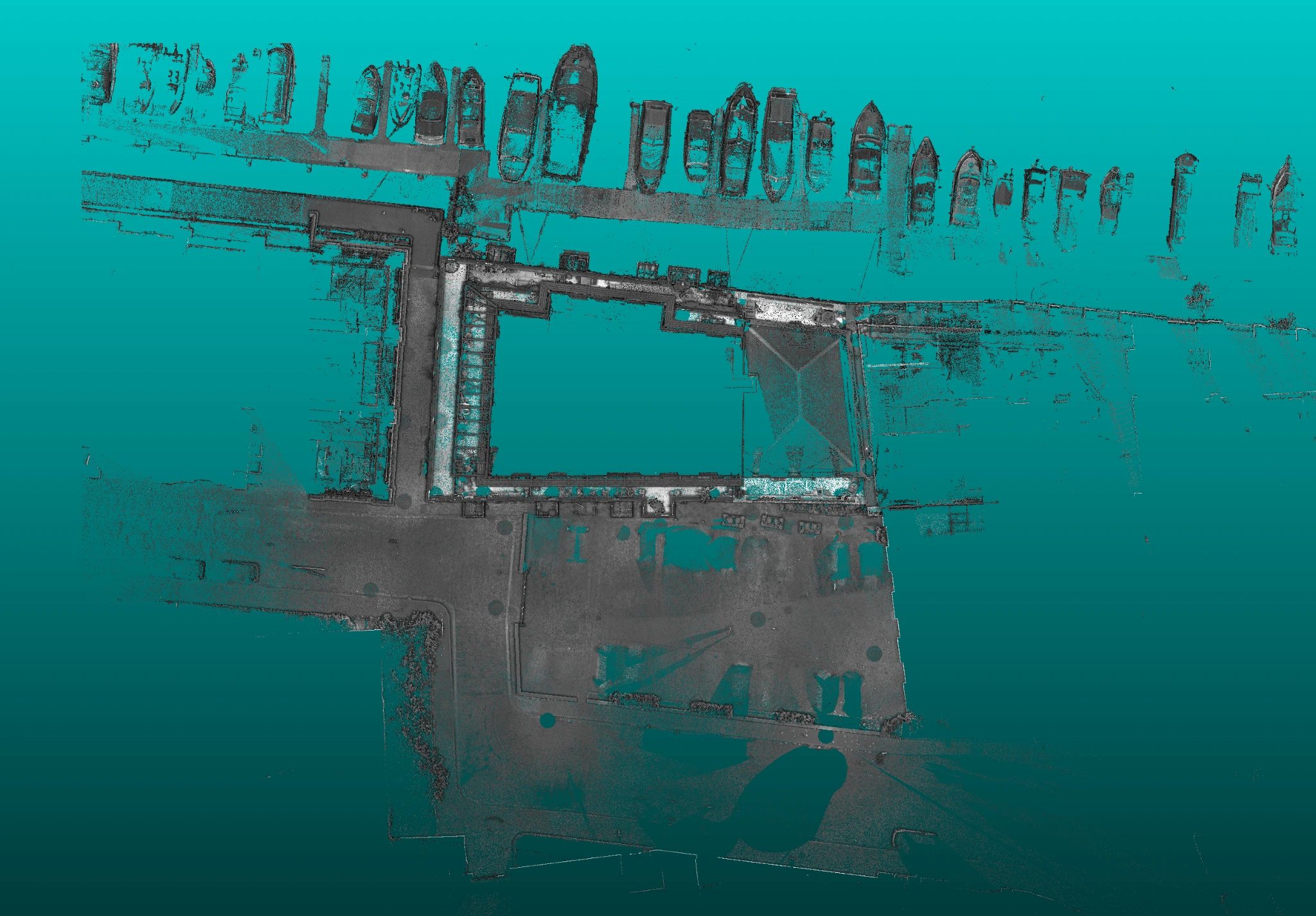
The overhead point-cloud view places the building, canal, bridge and surrounding captured surfaces in a shared spatial context. It provides an overview of the recorded site geometry; individual scan positions are not identified.
Refining the registration around relevant geometry
Geo Scan removed points from the high-level scans for the refinement stage so the registration used the retained ground-level common geometry, rather than the full 360-degree context. The registration was then refined and inspected again.
This was a processing decision about the geometry driving the alignment. The intended next step was to reconnect the refined scans to the ground-level scans with their full points retained, check that combined dataset and export the refined coverage for the elevations.
Because the retained point set and the registration were changed together, the report comparison cannot isolate how much improvement came from each change. It shows that the resulting registration assessment improved; the visual inspection provides additional evidence that the subject alignment improved too.
What the before-and-after registration reports show
Both original reports contain 51 scan stations. For a fair connection-level comparison, reciprocal entries were counted once and the analysis used the 206 unique station pairs present in both reports. The refined report contains one additional pair, which is excluded from the matched-pair statistics.
The first carousel image places the original Station 004–039 rows together for a direct comparison. The next two images show the full Station 004 excerpts rendered from the supplied reports. The error falls from 13.5938 mm to 6.5981 mm, while overlap stays close at 38% and 39%. Confidence rises from 81% to 91%. The full excerpts retain the other connections for context.
| Measure | Before | After | Change |
|---|---|---|---|
| Overall cloud-to-cloud error | 2.9575 mm | 2.4270 mm | 17.9% lower |
| Mean error across 206 matched pairs | 3.6540 mm | 2.9440 mm | 19.4% lower |
| Highest matched-pair error | 18.1385 mm | 15.3467 mm | 15.4% lower |
| Matched pairs above 10 mm | 17 | 7 | 10 fewer |
The 10 mm threshold is a comparison aid, not an agreed project acceptance tolerance. The software overall figure and the equally weighted pair mean are different measures.
| Station pair | Before | After | Reduction |
|---|---|---|---|
| 027–038 | 10.2170 mm | 3.7117 mm | 63.7% |
| 009–012 | 14.3886 mm | 5.8166 mm | 59.6% |
| 010–012 | 11.6792 mm | 5.0835 mm | 56.5% |
| 004–039 | 13.5938 mm | 6.5981 mm | 51.5% |
| 002–041 | 10.4383 mm | 5.3209 mm | 49.0% |
These are selected examples, not the complete network. Of the 206 matched pairs, 146 improved and 60 worsened.
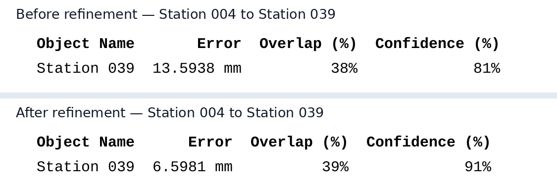
Direct comparison of original report rows: Station 004–039 has 51.5% lower reported error after refinement. Before and After labels identify the two source excerpts.
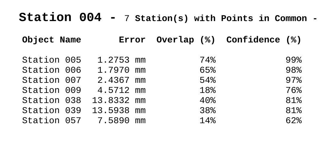
Before refinement: original Station 004 report excerpt. The connection to Station 039 reports 13.5938 mm error, 38% overlap and 81% confidence.
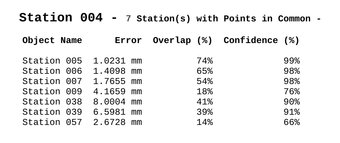
After refinement: the same Station 004 report excerpt. The connection to Station 039 reports 6.5981 mm error, 39% overlap and 91% confidence: 51.5% lower error.
Visual proof: checking the façade rather than just the score
The surveyor described the refined result as visibly much better during inspection. For panel-based elevation work, that check matters: overlapping edges and duplicated detail can make a dense point cloud harder to interpret even when the overall registration score looks acceptable.
The image slot below is reserved for genuine before-and-after views of the same façade area. Matching the viewpoint, scale and display settings will let readers inspect the panel joints and edges directly. Those screenshots have not yet been supplied, so no substitute visual evidence is presented.
The numerical review also identifies work still requiring attention. Seven matched connections remained above 10 mm. Two of those worsened slightly: 016–042 and 047–054. These connections need to be considered against the required output, the relevant geometry and the final QA checks.
Awaiting Geo Scan Image
Proposed alt text: Façade point-cloud detail before registration refinement at a recorded viewpoint and scale.
Before-refinement visual QA image awaiting supply. A matched view will show the original façade alignment.
Awaiting Geo Scan Image
Proposed alt text: The same façade point-cloud detail after registration refinement for direct alignment comparison.
After-refinement visual QA image awaiting supply. The same view will let readers inspect the change.
From refined scans to measured elevation drawings
The purpose of tightening the registration was to create a more dependable basis for interpreting the façade and preparing measured elevation drawings. A clearer fit helps the drafter distinguish real panel geometry from disagreement between overlapping scans.
The workflow continues by reconnecting the refined scans to the full ground-level data, inspecting the combined result and exporting the required coverage. The reports establish the refinement-stage result; they do not verify completion or acceptance of that later export.
Finished DWG elevation images provide practical output evidence. Genuine deliverable views will be added when supplied and checked. Drawings organise the agreed façade features into a measured reference for the design team.
Awaiting Geo Scan Image
Proposed alt text: Measured DWG elevation of the surveyed façade at Huller and Cheese, showing the agreed panel and opening detail.
Elevation drawing image awaiting supply and completion verification. Measured linework provides a reference for cladding replacement design.
Awaiting Geo Scan Image
Proposed alt text: Detail from the measured elevation drawing showing cladding panel joints and openings.
Elevation detail awaiting supply and completion verification. Panel joints and openings connect the survey record to the agreed drawing scope.
Orthographic façade images alongside the drawings
Orthographic images give the project team a direct view of captured surface detail. They complement the measured elevation linework by retaining the visible panel pattern, openings and interfaces within the recorded coverage.
The separate image collection below is reserved for genuine orthographic outputs and a detail corresponding to the drawing example. These outputs are awaiting supply and verification. They will not imply information about concealed layers or features outside the survey coverage.
Awaiting Geo Scan Image
Proposed alt text: Orthographic view of the surveyed façade showing visible cladding panels and openings.
Orthographic image awaiting supply and completion verification. A direct façade view shows the visible surface detail recorded by the survey.
Awaiting Geo Scan Image
Proposed alt text: Orthographic detail of the same cladding panel joints and openings shown in the DWG example.
Orthographic detail awaiting supply and completion verification. The matching façade area complements the elevation drawing example.
Where measured surveys fit into cladding remediation
Cladding replacement following the Grenfell Tower disaster sits within a wider building-safety programme. In England, the Fire Safety Act 2021 clarifies the scope of fire risk assessment for relevant buildings, including external walls. The Building Safety Act 2022 introduced wider reforms; the duties applying to a particular building depend on its circumstances.
EWS1 is a valuation and lending process rather than a statutory safety certificate. Fire risk appraisals of external walls use PAS 9980 where appropriate. These processes are distinct from a measured façade survey.
Geo Scan supplies visible building geometry and agreed survey outputs for the appointed project team. A measured survey can support cladding replacement design and information coordination, but does not establish material combustibility, inspect concealed cavity barriers or replace specialist fire-risk assessment. The statutory classification of Huller and Cheese is not asserted here.
EWS1 and the role of survey information
Laser scanning and building-safety information
Was the registration refinement worth the effort?
Yes, the available evidence supports the effort. The overall reported error reduced, the matched-pair mean improved and several weaker connections improved substantially. The surveyor’s inspection also found visibly better alignment on the subject required for the drawings.
The practical lesson is to review the registration network in relation to the deliverable. Dense coverage and good neighbouring connections are useful, but they do not remove the need to inspect weaker links, control which geometry drives the fit and check the resulting façade detail.
The next acceptance point is the final combined dataset and its outputs. That review should confirm the retained detail, any coverage gaps, the agreed drawing requirements and whether the remaining residuals are suitable for the intended use.